![]()
![]()
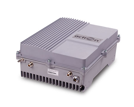
The TETRA Band Selective RF BDA is designed to provide a more cost-effective solution than adding a new Base Transceiver Station (BTS) to improve signal coverage and communication quality in TETRA system. And its easy installation and maintenance can help carrier get fast return.
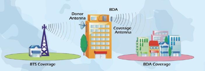
The TETRA BDA is working as a relay between the BTS and mobiles. It receives the low-power signal from BTS via the Donor Antenna, linearly amplifies the signal and then retransmits it via the Coverage Antenna to the weak/blind coverage area. And the mobile signal is also amplified and retransmitted to the BTS via the opposite direction.
Below is the TETRA Band Selective RF BDA application diagram:
Technical Specifications:
| ITEMS | SPECIFICATIONS | |
|---|---|---|
| Frequency Range | Uplink | 385~390MHz |
| Downlink | 695~400MHz | |
| Bandwidth(SAW Filter for UL&DL) | 5MHz | |
| Gain | 90±3dB | |
| Maximum Output Power | Uplink | 30±2dB |
| Downlink | 43±2dB | |
| In-band Flatness | ≤4dB | |
| Gain Adjustment Range | 1~31dB@Step 1dB | |
| Maximum Input Power(non-destructive) | 10dB | |
| I/O Impedance | 50Ω | |
| Noise Figur | ≤5dB | |
| System Delay | ≤5μSec | |
| VSWR | ≤2.0 | |
| Spurious Emission | 9kHz~1GHz: ≤ -36dBm/30kHz | |
| 9kHz~1GHz: ≤ -36dBm/30kHz | ||
| Third-order Inter-moduleation | ≤ -15dBm/30kHz | |
| RF Connector | N-Type(Female) | |
| Power Supply | AC220V | |
| Operating Temperature | -10℃~+50℃ | |
| Relative Humidity Range | ≤95%(non condensing) | |
| Dimensions | 428x328x175 mm | |
| Mounting | Wall mounting | |
| Weight | ≤15kg | |
| Aplication | Indoor or Outdoor(IP65) | |
| Remote Control Module(optional) | Wireless Modem(GSM) | |
| NMS Monitoring Function(Optional) | Real-time alarm for door status, temperature, power supply, VSWR, etc; Remote control such as turn on/off, increasing/decreasing output power etc; Real-time status for output/input power, UL/DL gain, all status of BDA etc. | |
![]()
Action Technologies is a professional manufacturer and solution provider of RF system. Our products, including MDAS, RF BDA/repeater, IBS and PMR as well as NMS software system, cover in more than 100 cities and 30 countries in the world. We are dedicated to provide best quality infrastructure and total solution to mobile operators and enterprises to enhance the trunked radio/cellular network.


Contact Action:
Phone: +86-755-86238970
Mail: info@action-tek.net
Fax: +86-755-26495994
Skype: action.technologies
Copyright © 2014 Shenzhen Action Technologies Co.,Ltd. All rights reserved.